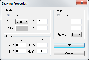
The Drawing Properties screen will display. Under Grids, specify the grid spacing. This will help locate the cursor easily on the screen. For example, if the grid has 25 units in the X-direction and 25 units in the Y-direction, input 25 in the X and Y fields. Select the Active check box. You can also select the line type and color for the grid.
Next, specify the drawing limits so the drawing will be within the drawing area. If the overall size of the section is 500 in x 600 in, the drawing limits in the X-direction are (-250, 250) and in Y-direction, (0, 600). So, under Limits, input -250 in the MinX field, 250 in the MaxX field, 0 in the MinY field, and 600 in the MaxY field.
Select the Snap Spacing. This will help produce an accurate drawing. This number is usually a small common denominator of the drawing dimensions. For this example, the snap spacing is 10 in, so under Snap, select the Active check box and input 10 in the X and Y fields.
Click OK and return to the Section Drawing screen. The grid will be displayed with your grid specifications in the drawing area.